White Rodgers 90 113 Fan Control Center

Details About Brand New Honeywell Tradeline R8285 A 1048 Control Center Fan Controller 24v Honeywell Control Hvac
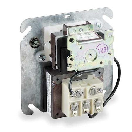
White Rodgers 90 113 23 18 Center Fan Control Zoro Com

M4 Lvunbqkewvm

Lg Electronics 6871a20999a Air Conditioner Main Pcb Assembly Take A Look At The Picture By Going To The Web L Lg Electronics Heating And Cooling Electronics

Amazon Com White Rodgers 90 130 Fan Control Center 503634 Home Kitchen

White Rodgers Pcbbf122s Integrated Fan Control Board Replacement Household Furnace Control Circuit Boards Amazon Com
White rodgers 15 23 49 each add to cart.
White rodgers 90 113 fan control center.

Emerson Electric Heat Sequencer 2 Switch Emerson Electric Electrical Supplies Electrical Switches

White Rodgers 90 342 240v 2p Relay Amazon Com

Emerson Electric Heat Sequencer 2 Switch Emerson Electric Electrical Supplies Electrical Switches

Amazon Com Emerson 16e09 101 Electronic Temperature Control Home Improvement
Source : pinterest.com
